

When specifying a spring for a medical device, two questions need clear answers: will it fit the assembly, and will it deliver the required mechanical response? These questions are related, but they are not interchangeable. A spring can meet its dimensional requirements yet remain unsuitable for its intended function. Equally, a spring that produces the desired force may not fit correctly.
For helical compression springs, separating fit requirements from force requirements helps design and procurement teams communicate design intent, assess competing constraints and define appropriate acceptance checks.
Dimensional requirements describe the spring’s physical geometry. For a compression spring, key dimensions include wire diameter, outside or inside diameter, and free length. End configuration and solid height — the length of the spring when the coils are fully compressed together — also affect installation and available travel.
Wire diameter is the thickness of the wire forming the coil. Outside diameter is measured across the outer surfaces of the coil, while inside diameter describes the opening through its centre. Mean coil diameter is measured through the centreline of the wire and, for round wire, equals the average of the outside and inside diameters: Dm = (Do + Di) / 2. A drawing should state which diameter is specified rather than using “spring diameter” without clarification.
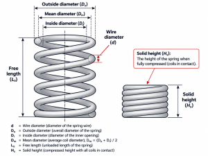
Figure 1. Key dimensional terms for a helical compression spring.
Free length is the spring’s overall length when no external compressive load is applied. It provides a reference for calculating deflection but does not establish the force the spring will produce when installed.
The outside diameter must provide suitable clearance within a housing, while the inside diameter may need to accommodate a guide rod. Clearance should account for dimensional tolerances and changes during compression, not simply the nominal unloaded dimensions.
Our compression springs information identifies wire diameter, spring diameter, free length, compressed length and required load as relevant design inputs.
A force requirement should identify the working position at which it applies. This might be the force required at a specified compressed length or at a stated deflection from free length. “Required force” alone does not provide enough information to assess a spring.
Spring force is not the same as spring rate. For a spring behaving linearly over the relevant working range, rate describes the change in force per unit of deflection, commonly expressed in newtons per millimetre (N/mm).
Within that range, the change in force equals the spring rate multiplied by the change in deflection. For a conventional compression spring operating within its linear range, free length, working length and spring rate therefore help establish the expected load at a given position.
An installed spring may already be compressed before the mechanism begins its operating movement. That initial compression creates preload. Further movement changes the force from this installed value, rather than starting from zero.
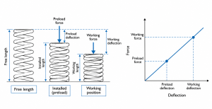
Figure 2. Free length, preload and working position shown against a linear force-deflection relationship.
Spring rate depends on wire diameter, mean coil diameter, the number of active coils and the material’s shear modulus. These factors interact, so specifying a material or wire size alone does not establish the spring’s response.
Where behaviour is nonlinear, a single rate may not describe the full movement. Specify the force at important working positions or agree an appropriate force–deflection requirement.
A dimensional tolerance sets the permitted variation in a physical feature. A force tolerance sets the permitted variation in load at a defined working position. One cannot substitute for the other.
A spring may satisfy a free-length tolerance but fall outside the required force limits at its installed length. Conversely, meeting a force requirement does not confirm that the spring will clear its housing or locate correctly on its seating surfaces.
Force requirements should therefore include the target or permitted force range, the corresponding compressed length or deflection, and relevant test conditions. Where deflection is referenced to measured free length rather than a fixed overall length, make that distinction explicit.
Avoid assigning tight tolerances to every feature without considering function. Identify which dimensions control fit and which force points control mechanical performance, then agree whether the combined requirements are achievable.
Dimensional inspection checks whether physical features meet specified limits. Force testing checks the spring’s response at defined positions under agreed conditions. Passing one check does not automatically establish compliance with the other.
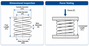
Figure 3. Dimensional inspection and force testing verify different aspects of spring performance.
Acceptance requirements should identify the checks needed, the measurement references and any relevant loading or conditioning procedure. If performance depends on repeated cycling or exposure to operating conditions, an initial dimensional and force check alone cannot establish performance throughout service life.
Available travel also needs attention. The maximum working compression should allow appropriate clearance from solid height and remain within the design’s permitted stress limits. Neither free length nor spring rate alone establishes a safe working travel.
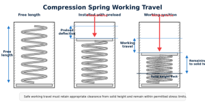
Figure 4. Free length, preload, working travel and remaining travel to the solid-height limit.
Provide the information needed to assess both fit and response:
Mark unresolved information as provisional. If space, dimensional limits and force targets compete, explain the priorities before finalising the specification.
For medical-device projects, component inspection alone does not establish suitability for a particular medical use. Material and, where applicable, biocompatibility requirements, cleaning or sterilisation exposure, operating environment, and device-level verification and validation remain separate considerations.
To discuss your spring’s dimensional and force requirements, send your drawings and application details and one of our specialists will get back to you.
